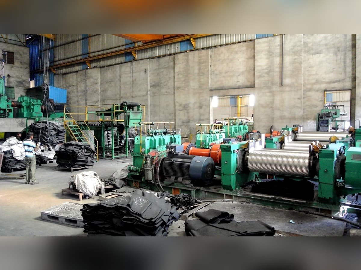
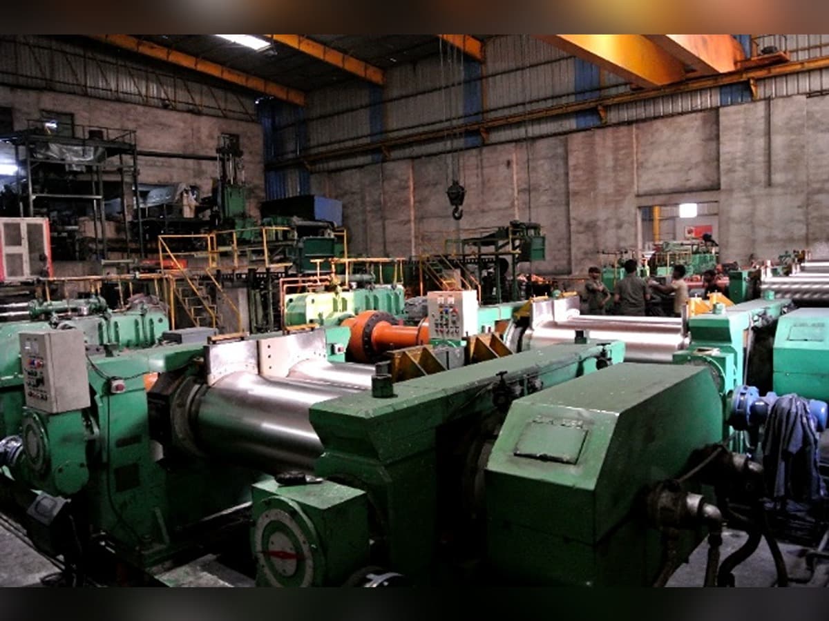
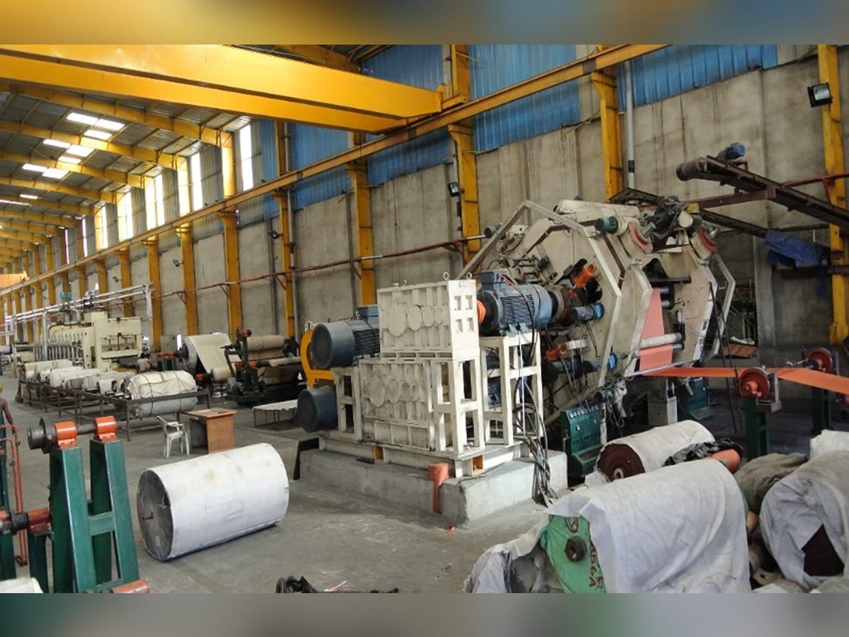
Stage Wise Process (Textile/Steel Cord Beltings)
A detailed walkthrough of SOMI Conveyor Belts Limited's end-to-end manufacturing process — from raw rubber to finished conveyor belt — highlighting the precision machinery and quality controls that define our product advantage.
Hydraulic Bale Cutting Section
- The bale cutting machine 1000 x 950 x 2170 (L x W x H) hydraulically operated unit which is used for feeding raw rubber in pieces to kneader.
- The machine cuts 50 Kgs of rubber into pieces in 1 minute and therefore, maximum capacity of this machine is 1,30,200 Kgs. in 3 shifts.
- The bale cutting machine helps in better productivity & safety for labours from using sharp knife.
Intermesh / Intermix Banbury Mixing
There are 3 Imported Intermesh & Intermix Machine with Hydraulic Ram Pressure through Station attached with 1100 HP / 380 HP / 350 HP ; heavy duty AC Motor through planetary gear with self lubricating and heat exchanger used in mixing chemicals / processing oil with raw rubber to yield desired properties. The compounding is done in two stages (Master and Final). The Master is first stage which is used to load only fillers to the rubber and subsequently after maturation time of minimum 48 hours the compound is once again fed into Intermesh / Intermix Banbury with final curing / vulcanizing agents before it is send to Supply Mixing Mill Section for further process.
The intermix is connected with Compressor (Atlas Copco) for Pneumatic operations for RAM Pressure while Hydraulic Station uses combination of Solenoid Valves for opening of discharge door. The temperature is digitally controlled using PID control system and maintained using cold water circulation / heat exchanges from dedicated 6 Nos of Chiller Unit of 68 TR dedicated to Intermesh / Intermix with additional Cooling Tower for II stage effective cooling.
The Intermesh / Intermix are connected to Dust Collector by vacuum pump and a leak proof filter vessel to collect all the blown out dust to clean the environment. The homogenous compound is drawn in sheet for using Dump Mill.
Cooling Rack with Chiller Plant
The conveyorized system of cooling rack has two section; It has combination of DC Motor from 1 HP to 5 HP for material handling and transporting to batch off unit:
- 1st Stage — rubber conveyor belt section from Dump Mill to Release Agent Mixed Water Bath.
- 2nd Stage — from Chemical Bath with Coolant to batch off unit using chain conveyor system.
The compound from Dump is immersed in liquid solution and subsequently passed through the tunnel of draft fans 10 Nos (3 Phase; 1440 RPM) to cool the hot compound. The significance of this operation is to ensure the desired properties of the rubber is retained without any chances of pre-scorching due to storage and thus ensuring our customers consistent quality throughout belt.
Supply Mixing Section (Cracker, Warmer & Supply Mill)
The Supply Mill Section has Combination of Cracker; Warmer and Supply Mixing Mill working on differential roll speed causing shearing force on rubber compounding through Shaft driven with High Torque Induction Motor with Self Lubricating Gear Box; The Unique Feature of Auto Cutting; Auto Nib Adjusting with In-built Heat Exchanger and Cold Water Running inside the Chilled Drill Rolls connected to Chiller Plants. Each Mill is supported by conveyor system using in-house conveyor belt for material transfer from one machine to another. For Safety every Mill has emergency brake system.
The Supply Mill section undertakes the responsibility to feed Calendar section as per scheduled requirements for rubberizing the fabric or to draw sheets for top / bottom cover. The Final compound from Intermix section is used after 48 / 72 hours of maturation / storage and re-orientation of magnetic field of compound.
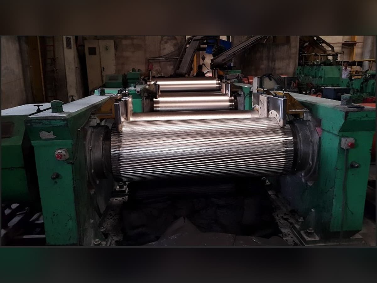
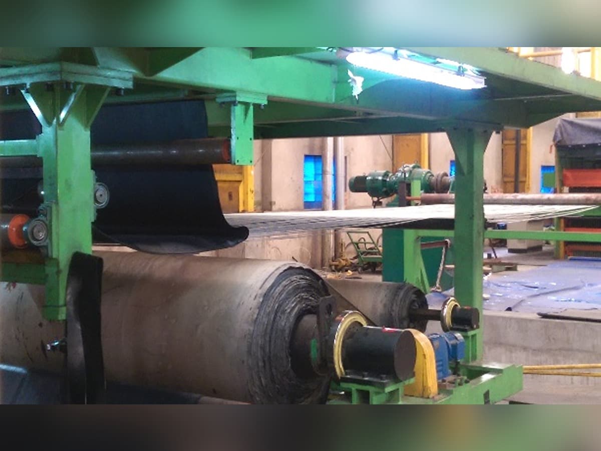
4 Roll S-Type Calendar Machine (2 Nos)
The Calendar Machine with 46 Installed Motors controlled by Computerized PLC Controlled A/C Drives is Imported from Farrel, USA 1488 rpm; 4 Roll coupled with 1:3 Gear Ratio. The state-of-the-art machine is used for rubberizing fabric using friction transfer process and to draw and rubber sheets for top and bottom cover using Optical Sensed and Auto Guide Rotary Cutters; The PLC also controls Auto Nib Adjusting through Servo Motors (8 Nos) for accurate thicknesses of transfer coatings. The Rolls are Chilled Drilled and connected to TCU for accurate Temperature Monitoring and Control and Individual Shaft Driven through Reduction Gear Boxes / Motor Coupling.
The output of 4 Roll Calendar machine is 345 meter/ hr. The calendar has special attachment for precision jobs and also to eradicate any humane-error problem using PLC controlled optical mirror sensed auto guiding, tracking system. All safety factors have been included in the most sophisticated calendar.
Since the rubber coating is done using friction process on hot rubber compound for better flow properties, hence the coated fabric has to be cooled before being batched up on auto web guided E & L (Germany) system using cold water circulated into Cooling Drums thru Reynolds Make Chiller unit of 68 TR capacity. This process, offers best maturation of the compound and thus avoid any pre-scorching problem once the post rubberized fabric is passed over the combination of cooling drum.
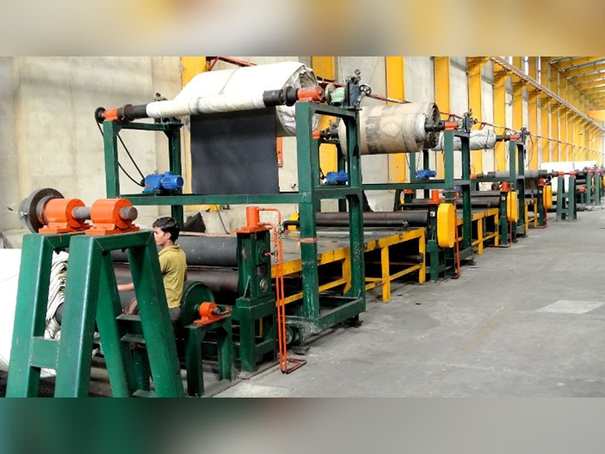
Conveyorised Building Table with Tension Braking Device
In building section, is specially designed using conveyor belt system to carry the carcass and handle the green belt like a new born baby thereby avoiding any chances of wrinkle formation. It has 4 / 5 Ply building station build on table having width of 2.8 Meter (Width) x upto 100 Feet (max) Long with heavy duty winders on each side.
The laminated ply after every Ply station (4 / 5 Nos) is followed by hydraulically controlled pressure rollers to release any air trap between the plies and thereby ensuring no air-bubble formation after curing. The ply stations attached with Auto Tension pre-set hydraulic controlled device move side ways for 100% edge to edge ply lamination and is controlled from the main panel. The extra width of the carcass is cut using adjustable knife mounted on table itself.
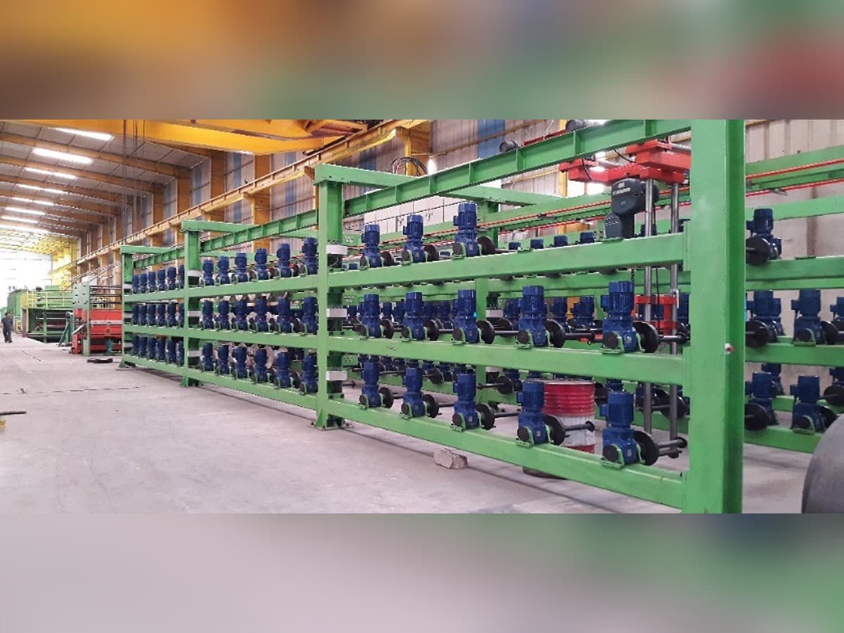
Creel Station
- It is a frame structure having spindles attached to the frame on which the creel containing the wounded Steel & Textile Cords are mounted.
- Every spindle in turn is equipped with a very specialized precise servo torque braking motor and reducer to apply initial tension and back tension for Steel & Textile Cord for accurate and unified movements (rotation) of creel together.
- Creel is a bobbin like structure on which Steel & Textile Cords are mounted.
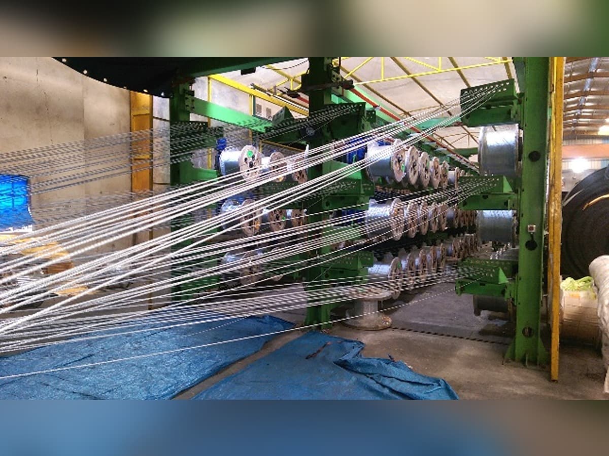
Tension Station
For unified Tension in All Cords for perfect structure : It is after the Creel Station consist of Hydraulic Clamping, Tensioning Device attached to Hydraulic Cylinders, Pull Back Hydraulic Cylinder and Pulley group. The hydraulic pressure for functioning of Hydraulic Cylinders is controlled by Hydraulic Station that uses combination of solenoid actuated valves for even pressure distribution trough-out the circuit under controlled parameters and hence in turn guarantees constant tension by virtue of cylinder ejecting force.
- The main function of Tension Station is to impart exact constant equal tension to each cord individually passing through the Creel Station to Comb Positioning Device.
- Moreover, Tension Unit shall also take care of thermal expansion of cords due to heat during vulcanization.
- The Equally Pre-Tensioning of each Cord is very important for straight running of Steel & Textile Cord Belt and for equal load sharing during the Operations.
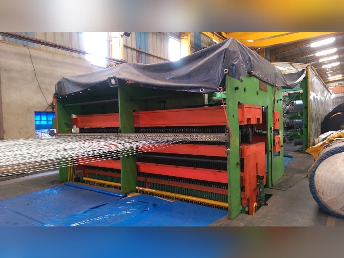
Swing Type Fixed Comb Device for Guiding & Positioning of Cords
For Accurate Cord Positioning & Auto Guiding : It resembles a comp like structure, where-in each hole / opening of the comb is a assigned opening for one single cord drawn from the creel. Similarly for every cord there is specific assigned hole (opening) in the swing type comb device to position or guide the cords in such a manner that they run parallel throughout and avoid any overlapping of cords and hence can be rightly termed as a accurate positioning & guiding device for Steel & Textile Cords.
- Comb plate has unique feature of complete R & I adjustment and hence can turn forward 90 degree. This R & I design is convenient to make the Steel & Textile Cord cross and change the comb plate.
- The comb plate needs to be changed with rating of belt (KN/M). Higher the rating the higher the diameter of the cord and subsequently the comb's hole diameter will change accordingly.
- Hence the comb hole diameter is directly proportional to rating of the belt. The rating of the belt shall also determine No. of Cords to be laid across the width as per pitch of the spacing between each cord.
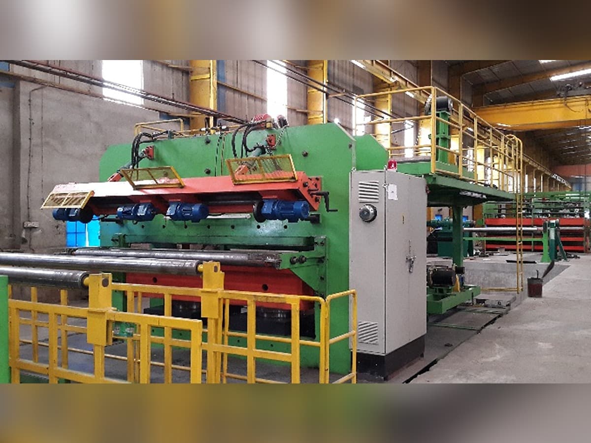
Building Machine
Lamination Station for Sandwiching Cords Between Top and Bottom Rubber Cover (Sheet) : It is used to lay Top Cover and Bottom Cover (Sheet Drawn from 4 Roll Calendar) on either side of the Cords and compacted by Pressuring Device using Hydraulic System attached to Hydraulic Power Pack for optimum consolidation and also build the plies automatically according to customer requirement, there is a center device on building machine center line that can ensure the movement reliable and stable and further one set of refining comb device which can use even distribution of Steel & Textile Cord rope during building. This is attached with Auto-centering Device to keep the un-cured belt in the centre of operation. Due to Hydraulic Pressuring Device the air-entrapment between the belt covers and Steel & Textile Cord is eliminated as air is release before the layers are bonded with cords in between.
Inspection Device
- This device driven by motor is used for checking green belt prior to vulcanizing / curing.
- With a remote controlled moving platform for online inspection.
- With auto centering and guiding system.
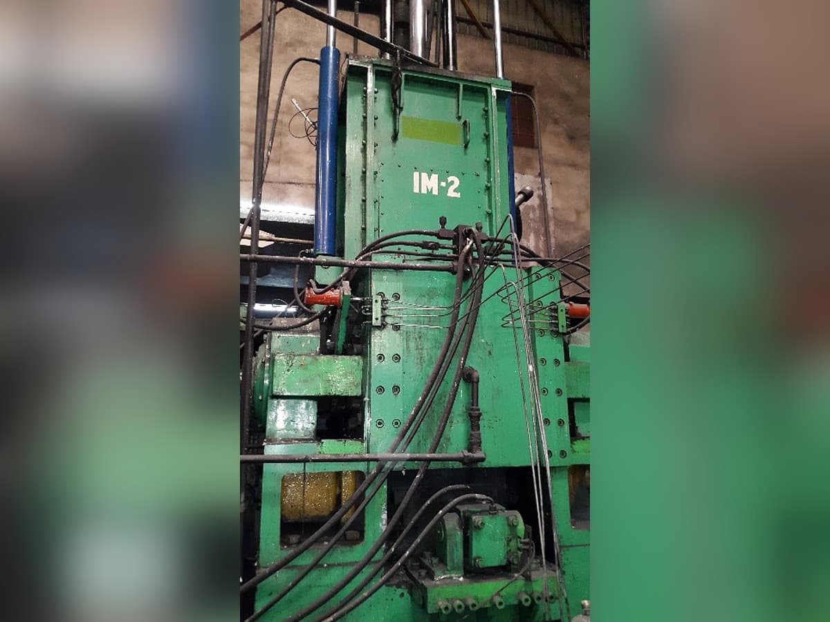
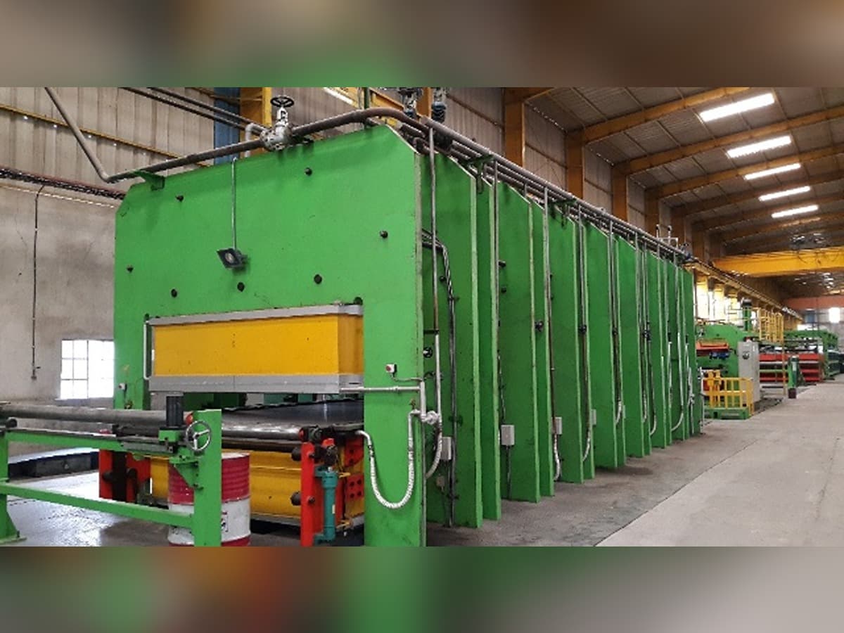
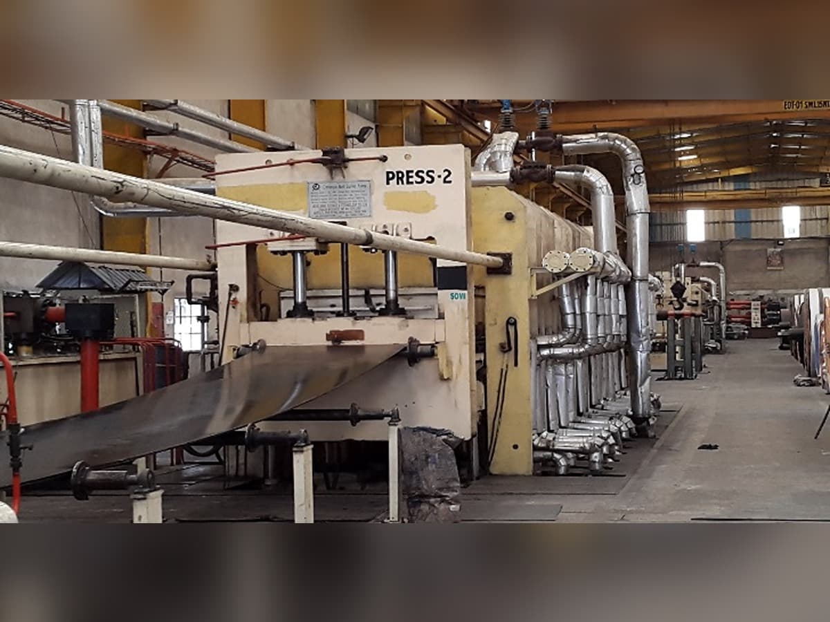
PLC Controlled Touch Screen Curing Presses
SCBL has distinction of being the only conveyor manufacturing unit in India using the sophisticated vulcanizing technique using 24 (3 / each row x 8 rows) Ram hydraulic cylinder enabling precision thickness control across the width due to accurate pressure distribution across the platen of 2200mm Width x 10.6 Mtr Length & 2600 mm Width x 10.6 Mtr Length. The press is automatically controlled with PLC system for the variables like temperature; pressure & time using touch screen functions.
The press is supported by Themax make Thermopac (Hytherm Oil) for uniform heating and Reynolds Chiller 68 TR capacity for end cooling. The system is 100% PLC controlled with hydraulic station comprising of three stage using combination of solenoid valves actuated / controlled by electronic panel having facility for computer interface for auto detection of electric problem, if any.
The main panel has total in-build control system for pre and post stretching device with hydraulic control and auto winders and guiders. The temperature is maintained using digitally controlled gate valves. In curing section, generally requires 16 - 45 minutes depending upon grade, thickness and width of belt. Each cycle cure is 9.75 / 10.6 Meter.
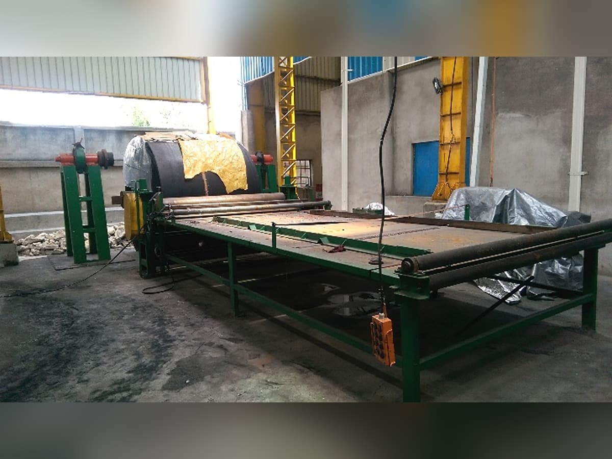
Cutting Table / Inspection / Sampling / Repair / Packing
The Cutting table is has on-table multiple cutting device of 2600 mm x 500 mm size and 25 ft. Long table for cured belt edge cutting, visual inspection and packing in one operation of conveyor belts on surface winding. The belt is send to hydraulically operated repair press for spot repair press for repairing minor defects in the belt. This section also has tools and tackles required for repairing. The ½ M sample is drawn from one end for laboratory testing as per QAP.